|
In today's networks, telecommunications and industrial system in high-speed signal transmission is the best method of using optical fiber module and optical fiber cable. Design engineers are developing with high speed data transmission cable and a copper interconnect solutions. When the speed reaches over Gbps, or transmitted over a distance of five meters, the design engineer must solve the fiber module engineers face design. This article will explore the optic module circuit design, and discuss how this circuit is applied to the high speed cable interconnect and a backplane design.
Figure 1 is a typical small size pluggable optical module ( SFP ) of the internal circuit. In this module, the signal is sent through the optical device ( TOSA ) is sent out. TOSA from the laser diode driver chip driver, the driver chip is required to maintain the TOSA bias current, and quickly drive laser diode to transmit data representing the optical pulse. The receiving end for receiving optical device ( ROSA ), which is composed of a receiving PIN diode and a transimpedance amplifier ( TIA ). TIA convert light energy into electrical signals.
When the optical link long or the output power of the laser is low, ROSA TIA output will be a small swing signal, then the need in the TIA after using a limiting amplifier on the TIA signal can predict the amplification, regardless of the input amplitude.
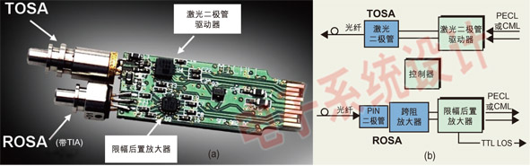
The amplifier 's main function is to the lowest noise amplify small signals, and output provides a standard logic level. Post amplifier can transmit a peak-to-peak voltage (hereinafter referred to as the voltage peak value ) down to 5mV differential signal, and the amplified as a standard CML or LVPECL logic level.Optical module behind the high-speed serial chip can reliably on an ROSA input signal level "amplification " decode.
When two or more frame needs to use copper cable is connected, the amplitude of the signal will beattenuated. Attenuation depending on the used copper wire, signal velocity and length of cable. For example, RG-174 coaxial cable attenuation amount is 1.3dB/ m @1.5GHz. Therefore, 10 meters of cablewill generate 13dB attenuation. If through 10 meters of RG178 cable in 1.5MHz frequency to send 400mVdifferential signal, output to 90mV.
LVDS, CML and LVPECL devices are difficult to decode a signal below 100mV. In 10 meters of RG-174cable as an example, the distal end of the signal will be very difficult to decode ( if possible ). When thecable signal frequency is increased, allowing the cable length is shortened. Therefore, along with thesignal frequency increased, before transmitting the 400m differential signal will rapidly decreased tobelow 100mV.
Limiting amplifier input signal can predict to enlarge to the appropriate CML or LVPECL level, even if theinput level of only 5mV. The power amplifier is used in signal detection ( SD ) or loss of signal ( LOS ) pin.This pin will be loss of signal or receive a valid signal warning. Can adjust the pin to set the peak level,gives the SD or LOS instructions, which will increase to diagnostic function in high speed system. Figure 2 gives the amplifier 's structure and executive function.
The limiting amplifier for transmission distance of 1 meters back solutions ( including a plurality ofconnector and the expansion card ). Will post amplifier placed far to the location, the system design can effectively eliminate the sent data or clock failure. However, sometimes the fault eye large attenuation, soto reproduce the original signal is the only way to use the low noise amplifier. With the backplane speedincreasing, this method has become more and more important.
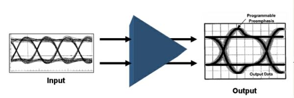
When the signal speed reaches 4Gbps~6Gbps, using the amplifier to recreate the attenuation of thesignal may not be enough to solve signal integrity problems, so the market has emerged a new band pre-emphasis functional devices, to drive the longer distance backplane interconnect. When the drive to the backplane transmit signal, these devices can in a very short time to amplify the signal rise along withincreasing slope. Figure 3 shows the band pre-emphasis driver working principle. Those at the rising edge of amplifying the amplitude can be adjusted and amplified duration controllable device having maximum flexibility.
In response to the transmission of high speed signal or long distance signal transmission challenge another solution is in the signal destination location increases the equilibrium ( EQ ). To the receiverincreases the equilibrium function is not a new concept, in the video and high-speed communication system using active or passive equalization for many years. A balanced benefits can reduce the reflectionand transmission medium loss compensation, in order to obtain the best input data reception.
When the speed of at least 4Gbps backboard while using the pre-emphasis and equalization effect is very significant. Figure 4 for the 6.4Gbps 223-1 PRBS pattern data in 1 meters of FR4 cable transmission of eye. The eye is in 1 meters of difference at the end of the cable two connector, a signal at the start, another is located in the signal terminal.
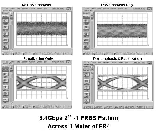
In 1 meters without pre-emphasis and equalization of the signal may be due to scattering, reflection and impedance mismatch and put in very big noise. Increase the pre-emphasis, signal began to eye certain characteristics, but the signal quality is not good enough. Once the receiver were balanced, 6.4Gbps signal is a very open. These trials show, receiver equalization is achieved by using the FR4 cable designengineer for long distance transmission of high-speed signal optimal solutions. In addition, when the pre-emphasis and equalization, will receive the lowest BER optimal signal.
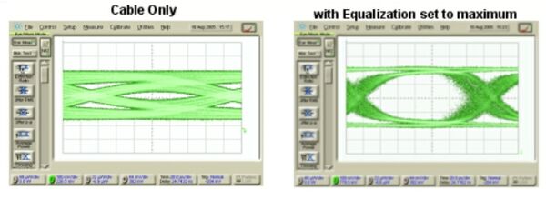
Another test at 5 m Amphenol SkewClear cable on. Figure 5 illustrates the equilibrium is to help rebuildthe available. 223-1 PRSB pattern data along the cable transmission, and in the distal part of the monitored. When adding the balance, signals can be reconstructed.
|

